We offer you sets of the device circuits and a method of winding coils to them.
Mishin Coil Circuits
Option 1.
Today, the most simple and reliable scheme has been developed by the author Denis Gorelochkin (nickname den737):
Option 2.
More complex scheme. All data and diagrams, a list of necessary details you will find in the archive below:
Self-made Mishin coils
In general, it is the geometry of the coil that determines the quality and strength of the effect on the body (the electrostatic spectrum functions due to the geometry of the capacitance), the frequency is secondary, but it is also important and lies within 250-380 kHz – this is for current coils.
This range is derived from practice. These frequencies and their fundamental harmonics do not affect the operating frequency of organs (less than 200 kHz) and body cells (more than 1500 kHz).
Frequencies less than 200 kHz cause arrhythmia. Cats adore 280-320 kHz, and they are excellent psychics (learn more about animals and medical disk). Our organisms react more to the frequency of 270-330 kHz and the maximum impact is approximately in the range of 280-310 kHz.
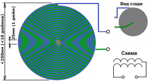
Figure 1 DMA
* Вид сзади – back view
*Схема – The scheme
*25 мм (1 дюйм) – 25 mm (1 inch)
*250 мм (<10 дюймом) – 250 mm (<10 inches)
Therapeutic disc (DMA) is designed to harmonize the processes of the whole body, harmonizes the aura. It is desirable to begin treatment with it.
For the manufacture of DMA, you need two identical flexible wires that need to wind a coil with a diameter of no more than 23 … 25 cm with an oscillation of the natural frequency (implosion point) of about 250-380 kHz. Coils more than 28 cm cause negative sensations, arrhythmia, i.e. you can get the opposite effect of the action! The internal diameter of the hole is 25 mm.
Manufacturing options from different wires:
- 0,2 mm.kv. the outer diameter of the wire with PVC insulation is about 1.0 mm. Then you will get the outer diameter of the disk 200-250 mm. If you get more than 380 kHz and higher, you need to add a few more turns to lower the frequency.
- 20 m of telephone 4-wire cable (remove the braid), a disk with a diameter of 21 cm with a frequency of 300-310 kHz will be obtained.
- MGTF wire, 25-25 meters with an external diameter of 0.9 mm. The disk is 210 mm in diameter. 278 kHz.
- wire in a varnish with a diameter of 0.5 mm, winding a disc with a diameter of 11 cm = 350 kHz, if the diameter is 11.6 cm = 283 kHz. If you fill it with PVA glue, the frequency can drop by 30 kHz.
- program for calculating the required length of wire
The base can be made from fiberboard or an old plate, on which double adhesive tape is stuck. You can use plexiglas for the base, but it screens external small vortices and they are not controlled. In the center, you need to make a hole where you will put a double wire, one of which will be fed (must be the same length).
And start winding the double spiral from the center clockwise (Figure 1), gluing the wires to the double tape. Do not use epoxy resin for fixing, which is a crystalline substance, it brings features to the work of the capacitive coil! At the end, under the wire, you can drill a hole, stick it out and fasten it with glue, so that the coil will hold better. You can also wrap it around with a wide tape or pour PVA.
Therapeutic torus (TMA) is designed to treat local problem areas, points. It has deeper penetration if compared to the disk.
To make TMA, you need a corrugation that is cut along and folded into the torus so that the outer cut side is on the outside (see fig.). The diameter of the inner hole of the torus should ideally be 1 inch (~ 25 mm), but variants with a slightly larger diameter are also possible, then the torus will perform with a little bit less power, but it can turn out to a different frequency, which is also useful in treatment.
The inner opening of the donut attracts the intensity of the impact. The smaller the diameter of the hole, the stronger the effect, but this is a strong load on the excretory systems of the body. The inner diameter must not be less than 25 mm.
The wire is UTP (this is a twisted pair for connecting the Internet). From this wire we get one twisted pair (double stranded wire) of length ~ 18 meters and we throw our torus. As a result, we get a kind of capacitor-inductance, the capacity of which is inter-turn (inter-wiring) capacitance, created by the insulation of twisted-pair wires and the gap between them.
Feed power to the beginning of one wiring and to the end of the other, and leave the remaining in the air (diagram in the figure 2).
- UTP wire – twisted pair from the computer cable. Length 15 m. Corrugate for winding should be approximately 2 centimeters. Fold it into the torus, the inner diameter is 2.5 cm. The operating frequency is about 300 kHz.
- UTP wire – twisted pair from the computer cable. Length of 16.5 m. Take the corrugation for winding about 19 cm in length. Fold it into the torus, the inner diameter – 3 cm, the outer one – 6 cm. The working frequency will be approximately 280 kHz. If wrapped with electrical tape, it reduces the operating frequency by ~ 6 kHz
- UTP wire – twisted pair from the computer cable. Length 18 m. Internal diameter – 4 cm. Wrapping coil is about 23 cm long.

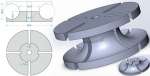
Figure 2
Tool for winding TMA (bagel, torus of Mishin)
*Гармонично, как в природе – Harmonious, as in nature
*50 мм – 50 mm
Setting and powering the Mishin coils
Power of Mishin coils (DMA and TMA)
To feed the device with a sinusoid to 24 Volts (amplitudes of half-waves to -12 … 12 Volts), i.e. the operating voltage at the output of the generator, without load (without a disk or torus) can be up to 20 – 24 volts, but maybe lower. Above 24 volts is should not be achieved, as the impact will be quite aggressive.
Under load (the disk or torus is connected to the generator), the output voltage from the generator can drop by a factor of 10 – depends on the capacitance of the wires (DMA / TMA manufacturing quality). Quite enough power is 2 W (amplitude) for conditionally painless withdrawal of complex diseases.
To measure the power, it is necessary to use a 1 Ohm resistor (Fig. 4) connected in series to the disk (or torus), i.e. we measure the oscilloscope drop voltage on the resistor 1 ohm and the effective value of the sinusoid should be within 100 … 200 mV (mA). It is not necessary to increase the current in excess of 250-300 mV (250-300 mA). Free ends of the disk (torus) are insulated. Even with a power rating of 0.1 watts in static, about 500 volts can sit on them.
When the free ends are already “phitonics”, then this is clearly a search for power and it is necessary to reduce power, reducing the output voltage of the generator.
Configuring DMA and TMA
To adjust the manufactured coils, you should connect the end of the other and the beginning of one wiring, and search for current resonance – the maximum current flowing through the coil.
Option 1
We connect the oscillator and oscillograph to find the implosion point. Changing the frequency, we look at the span of the sinusoid that moment when it is minimal – this is the point of maximum consumption, i.e. this is the operating frequency of the coil (when measuring, the frequency is shifted a couple of kHz downward due to the addition of the capacitance of the oscillograph probe!)
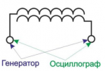
Figure 3
*Генератор – generator
*осциллограф – oscillograph
Option 2
For more accurate measurement, we connect the oscillograph to a 1 ohm resistor (Fig. 4), connected in parallel to the disk (or torus), i.e. we measure the drop voltage on a resistor of 1 ohm with the oscillograph and look for the maximum sweep of the sine.
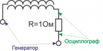 Figure 4
*Генератор – generator
*осциллограф – oscillograph
Option 3
If there is no oscillograph, then you can find the implosion point using two back-lit LEDs. On three fingers, wind a coil in 30 turns. Connect the ends to the back-lit LEDs (Fig. 5). By changing the frequency, search for the maximum burning of the LEDs, then reduce the amplitude from the generator again, search for the maximum glow of the LEDs changing the frequency and so until you find our working frequency (current resonance).

Figure 5
*Генератор – generator
After the transition of the resonant frequency, the process of absorption by the vortex begins, this is in fact for us a process that sucks out of the body bad structures. In other words, we need to find the resonant frequency (phase shift = 0) or just go above the resonant frequency (phase shift) for recovery.
To purchase the device, please, visit Buy it now
To find information about Mishin’s generator and its healing effect, please, visit About the Device